×

工业设计互动平台

手机短信,快捷登录

微信登录,快人一步

QQ登录

只需一步,快速开始

Modelling a Propeller using Rhino 3D

Q: Although propellers may look simple they are incredibly complicated in shape. Is there a secret to modelling a realistic propeller in Rhino? Nick Sills
When this question was received, my initial reaction was that it was going to be quite easy to create a propeller model, as I modelled simple impellers a few years ago for a previous industrial design project. After Nick sent over a Rhino file containing the engineering layout of the propeller he was having problems with, I suddenly realised that this was going to be a little more complex than I first thought! Nick’s major requirement is that he would like to use the model as part of a 3D Studio Max animation showing the propeller in action underwater. While the geometry will not be used as a CAD model for manufacture, it still needs to retain a certain amount of visual accuracy and should be modelled to quite a high definition, as it is the focal point of the visualisation.
As I always say with these kind of assignments, it is very important to have a good set of source material to aid with modelling. The complexity of the process would have increased ten-fold if I had not received the layout file of the prop. Even creating the geometry from just photos would have been difficult because of the very nature of the surface shapes involved. The file also provided actual pre-drawn curves, which I used in early construction, after re-orienting them all in 3d space. The best way to dissect a 2D electronic based layout is to choose the curves carefully and delete anything else in the scene such as dimension lines and crosshatching.
download the Rhino file containing the initial curves here (right click and "Save Target As...")
Then use the “Rebuild" command found in the Curves – Edit Tools menu, to reduce the point count on the lines. This is always important as creating models with too many initial points means that the resultant surfaces become over complex and are more likely to have errors. For example I rebuilt the prop blade edges to have 10 points with a degree of 3.
1.jpg
您需要登录后才可以回帖 登录 | 立即注册

本版积分规则

精彩回复

文明上网理性发言、请文明用语

carrot | 官方管理团队 | 发表于 2008-3-4 11:55:17
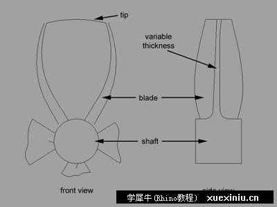
(1) Using the 2D rhino layout, relevant curves to aid in modelling are selected. Any other information such as dimension lines are discarded. At this stage it is best to Rebuild the curves to have less control points while still keeping curve definition. Notice how there is a variable thickness to the blades finishing in a smooth blend to the shaft, and how the sides of the blade almost curl around on themselves.
2.jpg
0 回复

举报

carrot | 官方管理团队 | 发表于 2008-3-4 11:55:30
(2) Next move and rotate the 4 blade edge profiles from the front view, 90 degrees around the center axis. Then turn on the control points and move them so they match the side view. To keep accuracy modify two curves on one side and the mirror around the center axis as these are symmetrical and delete the other curves. Next select the two thickness curves and rotate them roughly 45 degrees.

The easiest way to model the prop blades is to “Loft” a series of cross-sections. Lofting however, is the easy part; the difficulty comes in creating the cross-sections accurately. Prop blades not only twist outwards, but are also curved with variable thicknesses from base to tip. There is also the added complication of the blade being attached to the shaft and blended in the form of a fillet. Looking at this is enough to cause quite a headache! Luckily Rhino has a useful command called “Csec” which creates cross-sections from a series of profile curves. Choosing the profile curves was quite tricky, and I ended up using six profiles, which were the result of modifying some of the layout curves. The final blades need to be attached to the shaft in the form of a boolean union. This means that the base of the blade must intersect with shaft. This had to be taken into account when creating the csec profiles, and the “Extend” command was used with a curve, which was placed in the centre of the shaft acting as the boundary object.
3.jpg
0 回复

举报

carrot | 官方管理团队 | 发表于 2008-3-4 11:55:42
(3) This should now give you 6 profile curves as shown in yellow and gives a good representation of how the prop should look. Make sure that the base of the profiles intersects with the shaft. You may need to tweak certain curves either by moving points or using commands such as extend. Now use the \"csec\" command and select all the profiles in the right order as shown in the image above and draw the cross-sections in right or top views. Next loft these cross-sections.

The tips of the blades were created using a Rail Revolve, found in the Surfaces menu. The last cross-section in the loft was used as the path with the profile being created using the half of the blade tip curve from the layout. Rhino can be quite frustrating when performing boolean operations and I found that if I merged the blade and blade tip and then tried to perform a union of the complete blade with the shaft, the process would result in errors. The blade and tip were left unmerged and using a polar array I duplicated three sets equally around the shaft. The Cap Planar Holes in the Solid menu was then used on the blade as you need surfaces to act as solids for booleans, and the four blades and shaft were joined in union. I then exploded the surfaces and merged the blade tips, and then joined all the surfaces back together into a solid object. Finally I used the Fillet Edge tool in the Solids menu at the base of the blades and used a difference boolean to cut cylinders from the shaft.
4.jpg
0 回复

举报

carrot | 官方管理团队 | 发表于 2008-3-4 11:55:57
(4) Creating the blade tip requires the last curve in the loft to act as a rail revolve path. To create the profile curve, use the original tip curve from the layout front view, and split it in half. Then use Rail Revolve, found in the Surface menu to create the tip surface. Because of boolean problems later - do not join or merge the tip and blade surfaces. Instead for the moment select the blade surface and Cap Planar Holes, found in the Solid menu.
5.jpg
0 回复

举报

carrot | 官方管理团队 | 发表于 2008-3-4 11:56:12
Modelling a Propeller using Rhino 3D

Q: Although propellers may look simple they are incredibly complicated in shape. Is there a secret to modelling a realistic propeller in Rhino? Nick Sills

When this question was received, my initial reaction was that it was going to be quite easy to create a propeller model, as I modelled simple impellers a few years ago for a previous industrial design project. After Nick sent over a Rhino file containing the engineering layout of the propeller he was having problems with, I suddenly realised that this was going to be a little more complex than I first thought! Nick’s major requirement is that he would like to use the model as part of a 3D Studio Max animation showing the propeller in action underwater. While the geometry will not be used as a CAD model for manufacture, it still needs to retain a certain amount of visual accuracy and should be modelled to quite a high definition, as it is the focal point of the visualisation.

As I always say with these kind of assignments, it is very important to have a good set of source material to aid with modelling. The complexity of the process would have increased ten-fold if I had not received the layout file of the prop. Even creating the geometry from just photos would have been difficult because of the very nature of the surface shapes involved. The file also provided actual pre-drawn curves, which I used in early construction, after re-orienting them all in 3d space. The best way to dissect a 2D electronic based layout is to choose the curves carefully and delete anything else in the scene such as dimension lines and crosshatching.

download the Rhino file containing the initial curves here (right click and \"Save Target As...\")

Then use the “Rebuild\" command found in the Curves – Edit Tools menu, to reduce the point count on the lines. This is always important as creating models with too many initial points means that the resultant surfaces become over complex and are more likely to have errors. For example I rebuilt the prop blade edges to have 10 points with a degree of 3.


(1) Using the 2D rhino layout, relevant curves to aid in modelling are selected. Any other information such as dimension lines are discarded. At this stage it is best to Rebuild the curves to have less control points while still keeping curve definition. Notice how there is a variable thickness to the blades finishing in a smooth blend to the shaft, and how the sides of the blade almost curl around on themselves.


(2) Next move and rotate the 4 blade edge profiles from the front view, 90 degrees around the center axis. Then turn on the control points and move them so they match the side view. To keep accuracy modify two curves on one side and the mirror around the center axis as these are symmetrical and delete the other curves. Next select the two thickness curves and rotate them roughly 45 degrees.

The easiest way to model the prop blades is to “Loft” a series of cross-sections. Lofting however, is the easy part; the difficulty comes in creating the cross-sections accurately. Prop blades not only twist outwards, but are also curved with variable thicknesses from base to tip. There is also the added complication of the blade being attached to the shaft and blended in the form of a fillet. Looking at this is enough to cause quite a headache! Luckily Rhino has a useful command called “Csec” which creates cross-sections from a series of profile curves. Choosing the profile curves was quite tricky, and I ended up using six profiles, which were the result of modifying some of the layout curves. The final blades need to be attached to the shaft in the form of a boolean union. This means that the base of the blade must intersect with shaft. This had to be taken into account when creating the csec profiles, and the “Extend” command was used with a curve, which was placed in the centre of the shaft acting as the boundary object.


(3) This should now give you 6 profile curves as shown in yellow and gives a good representation of how the prop should look. Make sure that the base of the profiles intersects with the shaft. You may need to tweak certain curves either by moving points or using commands such as extend. Now use the \"csec\" command and select all the profiles in the right order as shown in the image above and draw the cross-sections in right or top views. Next loft these cross-sections.

The tips of the blades were created using a Rail Revolve, found in the Surfaces menu. The last cross-section in the loft was used as the path with the profile being created using the half of the blade tip curve from the layout. Rhino can be quite frustrating when performing boolean operations and I found that if I merged the blade and blade tip and then tried to perform a union of the complete blade with the shaft, the process would result in errors. The blade and tip were left unmerged and using a polar array I duplicated three sets equally around the shaft. The Cap Planar Holes in the Solid menu was then used on the blade as you need surfaces to act as solids for booleans, and the four blades and shaft were joined in union. I then exploded the surfaces and merged the blade tips, and then joined all the surfaces back together into a solid object. Finally I used the Fillet Edge tool in the Solids menu at the base of the blades and used a difference boolean to cut cylinders from the shaft.


(4) Creating the blade tip requires the last curve in the loft to act as a rail revolve path. To create the profile curve, use the original tip curve from the layout front view, and split it in half. Then use Rail Revolve, found in the Surface menu to create the tip surface. Because of boolean problems later - do not join or merge the tip and blade surfaces. Instead for the moment select the blade surface and Cap Planar Holes, found in the Solid menu.


(5) Create a solid cylinder to act as the shaft. Select the tip and blade and use Polar Array, found in the Transform menu to duplicate 3 further sets around the shaft every 90 degrees. Select each blade in turn and perform a union boolean with the shaft. Then use Fillet Edge, found in the Solid menu to create a fillet with a radius of 5 on the edge that connects the blade to the shaft.
6.jpg
0 回复

举报

carrot | 官方管理团队 | 发表于 2008-3-4 11:56:19
(6) Finally Explode the surfaces and delete the capped surface on top of the blade. Now select all the surfaces (including the tip surface) and use the Join command to weld them together. Next create cylinders and cut them out of the shaft using boolean difference. As a final touch fillet the edges of the shaft. One finished complex propeller!
0 回复

举报

山阴小卒 | 设计助理 | 发表于 2008-5-23 16:59:39
这个......英语觉得不好啊,看不明白[s:21]
0 回复

举报

yeoman99 | 实习生 | 发表于 2009-8-20 09:52:00
kan bu dong 4410@163.com
0 回复

举报

佳弦 | 实习生 | 发表于 2009-8-22 11:08:08
XUE XI ZHONG~
0 回复

举报

小郭 | 设计助理 | 发表于 2009-10-23 11:26:50
不看的话还真不知道
0 回复

举报

玉成 | 实习生 | 发表于 2009-10-23 12:07:23
太发了。不懂!!!!!!!!
0 回复

举报

heenfei | 实习生 | 发表于 2009-10-23 12:50:00
俺是菜鸟
0 回复

举报

woaikang | 实习生 | 发表于 2010-1-28 11:39:22
[s:137]
0 回复

举报

woaikang | 实习生 | 发表于 2010-1-28 11:39:51
[s:153]
0 回复

举报

woaikang | 实习生 | 发表于 2010-1-28 11:40:43
[s:65]
0 回复

举报

woaikang | 实习生 | 发表于 2010-1-28 11:41:08
[s:83]
0 回复

举报

woaikang | 实习生 | 发表于 2010-1-28 11:41:46
[s:40]
0 回复

举报

普天 | 体力透支 | 发表于 2010-1-31 17:40:11
太帮了
0 回复

举报

城市贫民 | 设计助理 | 发表于 2010-2-5 11:13:40
做得很好,就是看不太明白
0 回复

举报

f2831890 | 设计助理 | 发表于 2012-7-26 19:01:25
有文件供下载吗?
0 回复

举报

XIANGkeSI | 实习生 | 发表于 2012-10-13 07:22:32
楼主英语很好啊
0 回复

举报

yinjunmi | 实习生 | 发表于 2013-1-5 16:55:51
英语不过关,看不懂:'(
0 回复

举报

shark77 | 实习生 | 发表于 2013-1-7 16:33:38
如果能翻譯再清楚一點就好了
0 回复

举报

推荐学习